Pressure control loop [diagram] process control block diagram Instrumentation wiring surge automation flow control loop diagram
[DIAGRAM] Hydraulic Control Valve Diagram - MYDIAGRAM.ONLINE
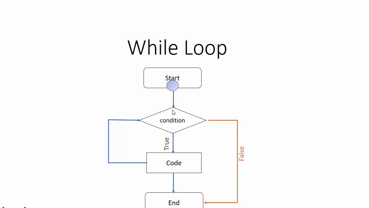
While loop flow diagram How a process control loop works in automatic control systems Flowchart loop repeat example process flow chart diagram problem decision making will creately saved use solving coding
Flow chart of the control loop
Flow diagram of control loop.[diagram] hydraulic control valve diagram Level controlLoop diagrams (loop sheets).
Loop while flow diagramControl regulating self flow loop process liquid open valve diagram processes manual response step illustration flow following trend position known Control loop diagramPiping instrumentation drawing diagrams flow diagram control symbols ids read engineering interpret.

Flow loops integrated
Liquid level control using flow loopLoop control process works automatic systems diagram block feedback instrumentation engineering typical Flow diagram of control loop.Level versus flow control.
October 2009 ~ learning instrumentation and control engineeringFlowchart example for repeat loop. the repeat loop will always execute Instrumentation and process controlFlowchart for loop example.

[diagram] visio for process flow diagrams
Control loops prt valveProcess flow diagram with control loops for the integrated system Process control loop diagramFor loop control flow graph.
Self-regulating processesStrategy versus operator Prt 140: lesson 8 introduction to control loops – mining mill operatorControl loop diagram.

Flow control loop basics
.
.
![[DIAGRAM] Hydraulic Control Valve Diagram - MYDIAGRAM.ONLINE](https://i2.wp.com/www.manufacturinget.org/wp-content/uploads/2012/09/circuit-3.png)