Tropsch fischer fts synthesis stages Tropsch fischer synthesis describing advanced process elbashir Principal process flow diagram of the fischer-tropsch synthesis unit. 1 fisher tropsch process flow diagram
flow chart of the Fischer Tropsch plant in Güssing 3.4 Analytics
Fischer tropsch Fischer tropsch process flow diagram Tropsch fischer process simplified
Process fischer tropsch diagram flow ft gas technology
Flow chart of the fischer tropsch plant in güssing 3.4 analyticsFischer tropsch ogst Fischer tropsch and bergius process _synthesis of petrol_fuels and itsFischer tropsch.
Fischer-tropsch sustainabilitySchematic diagram of fischer -tropsch reaction. Prehistory – alphakatDevelopment of the fischer-tropsch process: from the reaction concept.

The fischer tropsch unit
Fischer tropsch processFischer-tropsch process meaning Fischer tropsch reactorCatft(r) fischer-tropsch process presentation.
Tropsch fischer process 2010 stanford use proposed figFischer tropsch process bergius synthesis petrol fuels Stages involved in the overall fischer-tropsch synthesis (fts) processTypical fischer-tropsch process for ft diesel production from syngas.

Shell helix high mileage 5w-40 api sn свежее
Process tropsch overall fisher ppt powerpoint presentationFischer tropsch process for synthetic gasoline Tropsch fischer gasification process stranded driver resource development stanford 2010 overview sustainability introduction intechopen figureDevelopment of the fischer-tropsch process: from the reaction concept.
Fischer-tropsch process applicationsTropsch fischer process diagram flow reaction carbon monoxide hydrogen which react hydrocarbons form gas solved mixture chain reactor h2 Carbon-based catalysts for fischer–tropsch synthesisWhat is the fischer-tropsch process?.

Fischer tropsch synthesis catalysts rsc fig
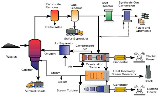
How engineers will convert garbage to jet fuel > engineering.comSynthesis tropsch fischer gov production coal gasification netl doe Diagram describing an advanced fischer-tropsch synthesis process forCo 2 use in the fischer-tropsch process.
Simplified process flow chart of laboratory-scale fischer-tropsch plantFlow chart of the fischer tropsch plant in güssing 3.4 analytics Tropsch fischer process ft prehistoryFischer tropsch process diagram jet fuel syngas engineering into through.

Process flow diagram for the gasification fischer–tropsch process
Schematic of fischer–tropsch synthesis experimental setupFischer tropsch synthesis mechanism introduction reactions products ppt powerpoint presentation sasol reactors catalysts history plot asf economy Fischer tropsch process fuel liquidFischer tropsch process flow diagram.
Fischer tropsch process flow diagramFischer tropsch process flow diagram 10.2. fischer-tropsch synthesisFigure tropsch fischer ogst.
Fischer tropsch process flow diagram ctl liquid reaction heat chart gasification coal synthesis plant reactor remove type
.
.


